- Removing/Simplifying the Rats Nest
- Removing the Oil Metering Pump (OMP)
- Removing the Air Pump, BAC, ACV
- Delete Everything
Removing/Simplifying the Rats Nest
The following material was taken from Carl at http://www.face2faces.co.uk/RX7/howto/ratsnest1.htm; however, at the time of writing, the page is not longer up. Hoping Carl is well.
Rat’s Nest Overhaul
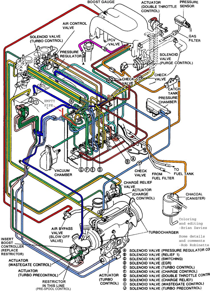
The RX7 uses a maze of vacuum and pressure lines to control the twin turbo system. These lines have a tendency to either chaff through on other engine parts, or bake and crack due to the excessive heat that the rotary engine produces. A crack in one of these lines can cause any number of problems, as they control absoloutely everything turbo wise.
When you find you have a boost problem, and that you are getting incorrect boost levels – one of these pipes is more than likely to blame.
When it comes down to actually replacing one, you may as well do the whole lot in durable silicon/viton hose. Silicon is adequate, but viton has higher resistance to temprature and oil.petrol. Reaplacing these hoses eliminates the chances of fixing one hose and having another split 2 weeks later. Replacing all the hoses is a long and laborious job, involving removal of many of the engines components including, but not limited to the inlet manifold, alternator, air pump, air filters, coils and parts of the cooling system. If this hasnt put you off already, keep reading.
In order to do this procedure, you will need lots of vacuum hosing, razor blades, normal tools, zip ties, and its also a good idea to replace your check valves as they tend to be leaky. I ordered my hosing from Rally design and i got:
1 x 4mm Vacuum Tubing (3m Pack) (VT4B-2W) = £5.70
3 x 3mm Vacuum Tubing (3m Pack) (VT3B-2W) = £16.20
1 x 6.3mm Vacuum Tubing (3m Pack) (VT6.3B-2.5W) = £8.10
1 x 8mm Vacuum Tubing (3m Pack) (VT8B-3W) = £11.70
This i believe should be more than enough for the whole job. In retrospect, i bought too much. I probably could have got away with 2 packs of the 3mm tubing, as i still have one left. The check valves i have not managed to source yet, as Mazda want nearly £25 each for them. I will however update this when i find a vendor for check valves.
Ok, now, onto the procedure!
Length of Procedure: Days…
Difficulty: 5/5
Note: Throughout this procedure it is VERY easy to snap parts you do not want to snap. As such, TWIST the tubes, dont yank them. If you do break them they can be repaired, but it is obviously best not to. As such, if you find a hose you cannot remove, try cutting it somewhere else so you can get it out of the car in an easier to remove position.
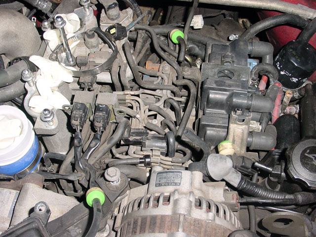
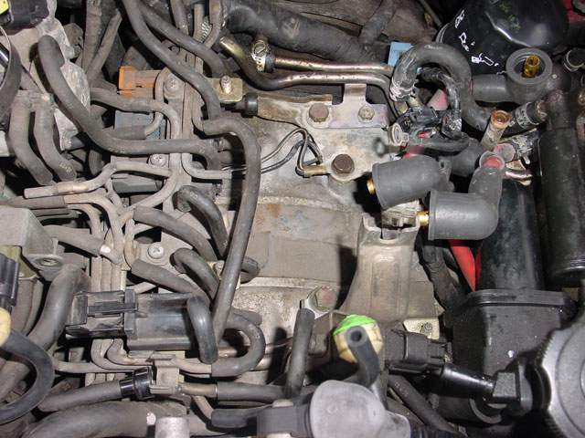
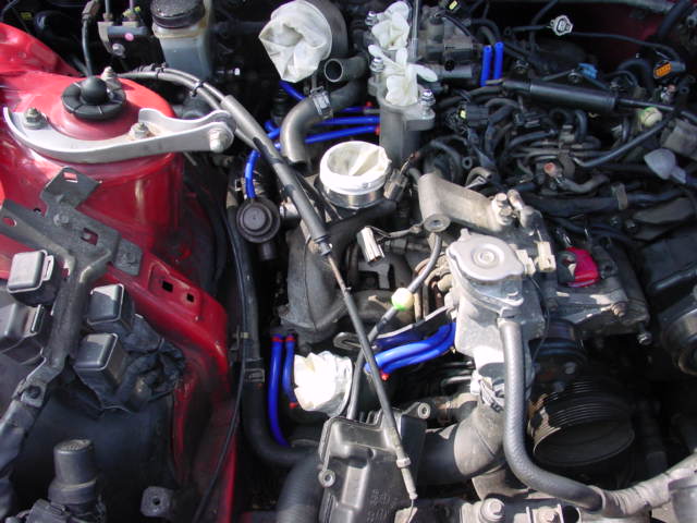
Remove your strut brace, and all of your boost pipes. Protect the boost pipes by stretching rubber gloves over them. Remove your inlet elbow and air filters. Now start on removing the inlet manifold. Undo the bolt at the front right hand side of the UIM. Remove the throttle cable, and disconnect the map sensor. Reach around the back of the UIM and disconnect all wires attatched to it and a couple of vacuum lines round there too. Undo the two 12mm bolts on the lifting eye and remove the earth straps. Disconnect the vac lines on the front of the UIM (should be four, one to the oil filler neck, one to the pressure tank, and a few others) after that, undo the bolts connecting the UIM to the LIM. After this, you should be able to lift the UIM off. Be careful here, as you do not want to snap any of the plastic nipples alot of the vac lines connect to. Here is one i made earlier…
And here is the rats nest in all of its glory. You will be replacing all of those pipes!

After you have got to this stage, you need to remove your ignition coils, remove the wires first. Its pretty simple to reconnect them right as the coils are labelled, so dont worry about marking them unless you expressly think you should.
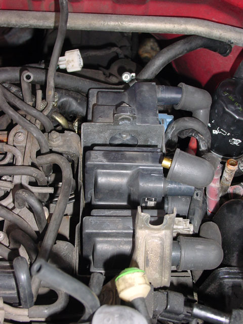
After removing the wires, remove the coil wires. The easiest way to do this is to press the tab with one hand and use a flatheaded screwdriver to turn in the gap and force the plugs off. Make sure you press the clips nice and hard or else they will snap when you pry them off with the screwdriver. See the screwdriver in the below picture. Notice also the “L1” and “L2” markings on the coil.
After this, remove the four 10mm bolts around the trap the coils attatch to, and also the 8mm strap holding down the earth strap on the leading plug coil. This is a little fiddly to get out, but once everything is disconnected it doesnt take too long.
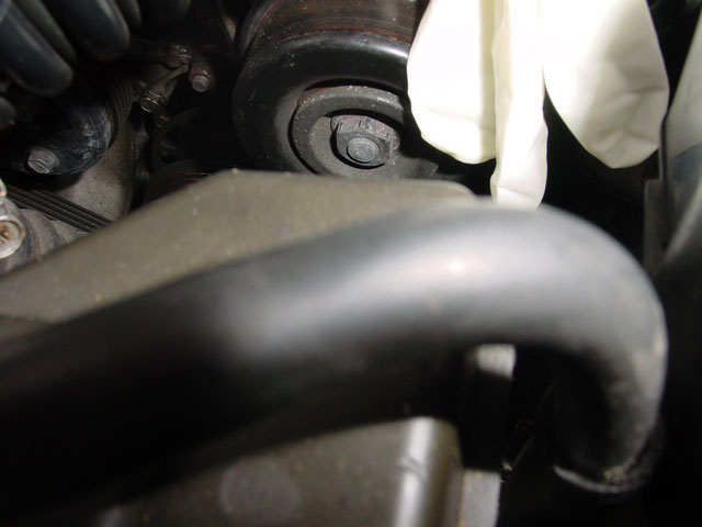
After this, you need to remove the two belts at the front of the engine. First you need to de tension them, this can be done by slackening the bolt on the power steering pump belt tensioner by a couple of turns. This will allow the tensioner to move. It is a 17mm nut and is under the intercooler outlet pipe. Remove this pipefirst as it makes access easier. The hose in the picture comes from the AST, to help you locate where you are looking.
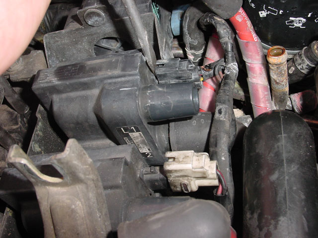
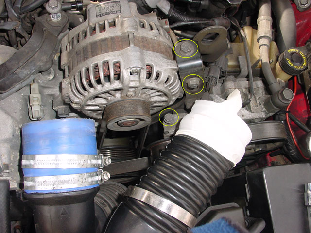
After this is done, you must then undo the remaining tensioner locking bolt, the alternator bolt and you can then begin to slacken the belts. The alternator tensioner locking bolt is circled below, it is the one in the middle. Undo this, and the bolt on the left of the alternator (just above the blue hose) then undo the remaining two bolts. This will slacken the belts.
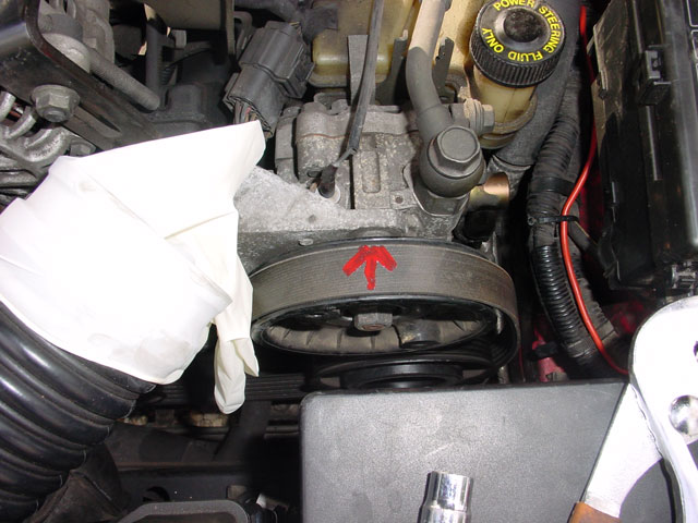
Once you have slackened the belts, mark them so you know which way to put them back on. I like to mark mine with an arrow pointing into the cabin, so i cannot get confused if i randomly forget which way the engine rotates :o)
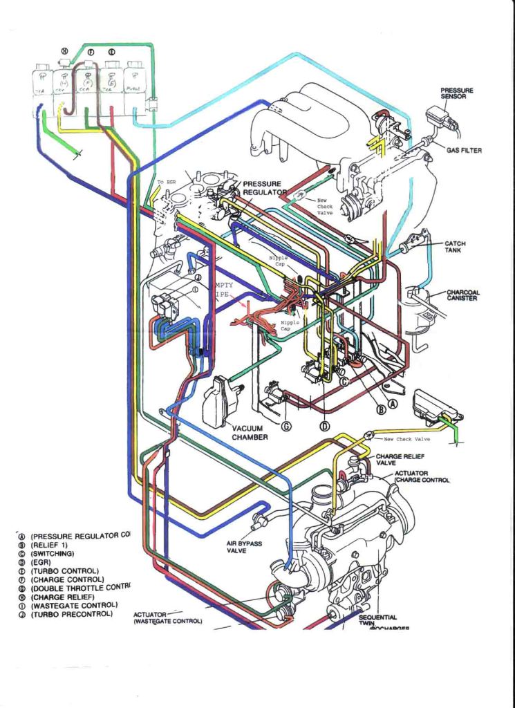
After this, the belts can be removed and you can begin removing the alternator and air pump. These parts require the removal of all bolts, the mounting brackets, wiring and then sheer brute force to remove them – they are on there pretty tight, and it may feel like you havent got the bolts out. After those are removed, you can begin working on the left hand side of the engine (drivers side for the USA) with the silicon hoses. Replace them one hose at a time and remember that the wastegate and secondary turbo precontrol hose have restrictor pills that must be added into the new hoses or you will get hardly any boost. See this image for a diagram. On the right of the pictures, you will see the lines marked with the pills in. When you remove them, look down them. You will see the pills and you will feel them if you run your fingers down the line. Cut open the line and install the pills in the new lines. You can use a boost controller on the wastegate line to regulate boost, but this is highly not recommended without a fuel computer. For an excellent guide on boost controll, see Rob Robinettes site.
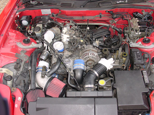
After this the side of your engine should look a little like this.
Now that you have all of the lines on the turbo side of the LIM done, its time to start snipping vac lines and disconnecting virtually everything in the car so that you can remove the solenoid rack. The first thing to do is to remove the three screws holding in the front of the solenoid rack. They are phillips screws and there are three in a row. Two to hold the solenoid rack on and one holding a small coolant hose to the rats nest. Be careful when doing this, as the screws are tight and you do not want to round them off, trust me – i’ve been there. After these three are out, there are some more on the back, you may need to remove some of the fuel lines to remove them.
Now you have lots of photos of how the solenoid rack went together, (because you took a bunch) and you have snipped all of the vac lines with some pincers (carefully! and after taking photos!) it is time to try and work out what the &*$! is still holding it in. I cannot help you here unfortunately, it is just a matter of having a good look round and removing things that get in your way. Removing the solenoid rack is a real pain in the ass but it is worth the effort once its all back in.
Ok, so now you have your solenoid rack out. Put it to one side. Don’t be surprised if you had to remove the oil filler neck and vacuum tank, along with quite a few electrical connectors and the air control valve module from the LIM. Once this is out, you can begin removing the fuel lines, and the mounting points brackets for other things that have been removed so long that you forgot what connects there.
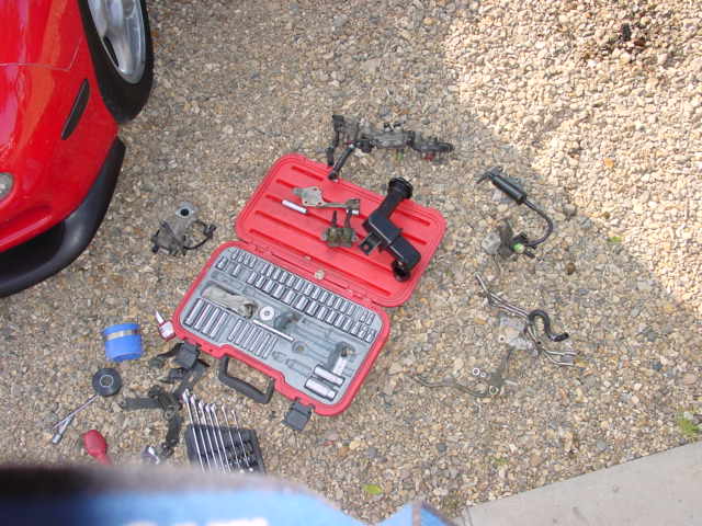
Once this is all out, disconnect your fuel rail, tie back your loom away from the rail (i used silicon hose tied to a post on the US passenger side to pull the loom away from the fuel rail) and remove the fuel rail carefully. Put this somewhere clean and do not allow any grit into it! You will now have various RX7 parts scattered around your feet…
After you have removed this, you will have access to the last few vacuum hoses on the car to change them. When you have done this, it is time to set to work on the solenoid rack itself.
Be careful when removing the old pipes here, i found the best technique to heat them with a lighter to soften them, and then slice the ends down their length with a razor blade enabling you to pry open the split with a screwdriver/razorblade. If you have a stubborn hose, twist it to “break” the seal, don’t pull it, or you will break solenoid nipples. I actually broke two of mine, and reattatched them with superglue afterwards. Although not ideal, i am confident this will hold.
Start replacing the hoses one by one, and only replace the hoses that you can do both ends of. The ones you had to cut (i.e the other half is still left on the car) break the “seal” of the pipe but leave where they are. This will help you identify what went where orignally but still allow you to remove the pipes easily when you need to..
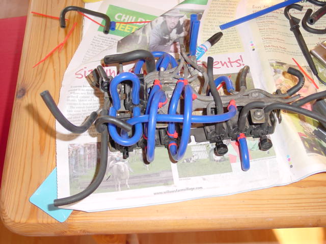
Once you have replaced all the hoses that you can and repaired the nipples where necessary/possible, your rack should look like this. Again, notice that i have left the pipes that connect to the car (rather than back to the solenoid rack) on the rack to make things easier when it comes to refitting. Remember to zip-tie the ones you do replace, though.
Now it is time to test your solenoids, this can be done by applying 12v to their terminals. You should hear a click. If you do not, the solenoid is broken.
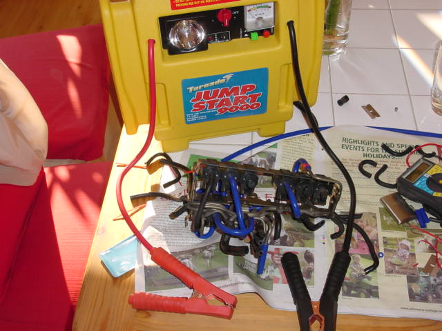
Here are the solenoids that i had to repair:
After this is done, replace any other hoses with silicon ones that you feel you should. (remember, silicone is NOT suitable for oil or fuel lines) I removed my fuel rail and loom and gave the top of the engine an inspection and clean…As you can see, the engine really does look like a barrel! The brown pipe on the left of the picture is the supply to the oil squirters, do not touch this! You can however, safely replace the black lines coming from the top of the squirters as these are the air supply.
After you have all the lines replaced that you feel you possibly can, it is time to begin re-assembling the car. Here is a picture of mine shortly after refitting the rats nest. When you do come to re-fit your own rats nest, spend 15-20 minutes just looking at it making sure all pipes are connected, and referring the to vacuum map to check they are all connected correctly. I suggest saving the image to your computer and printing it off in colour to allow you to work on the car. Trace each solenoid one by one, and check it is correctly connected. Be aware that some of the solenoids on the diagram may not be on your car (eg the centre one in bright yellow is for auto cars)
You took it apart, so there is no point in me describing how it goes back together as you already have an idea. Afterwards, you will have an engine bay that looks pretty similar, but you will be safe in the knowledge that all of your vac pipes have been replaced.
-Carl
Removing the Oil Metering Pump (OMP)
Another option when simplifying the engine for a swap is to remove the OMP. This is one of the many notorious features which cursed the RX7 and forced a bad wrap due to miseducation. This takes oil from the oil pan and injects it into the combustion chamber to lubricate the infamous apex seals.
While there are optional bypass kits which allow the OMP to pull from a dedicated reservoir, I will be sharing how to remove the system.
Removal of this system will require pre-mixing!
Block off kits:
- Banzai Racing: FD 13B-RE oil metering pump elimination
- Pineapple Racing: OMP Rotor Plugs and OMP Block Off needed
Common Pre-Mixes:
- Idemitsu
- Renewable Lubricants BioRacing
- e85/Methanol Only Redline Alcohol e85 2-cycle pre-mix
HOW MUCH TO PREMIX – taken from: Rotary Performance – To Premix Or Not To Premix
If the determination is that you have to premix, the obvious question is how much to add? Let’s go over a few factors. Turbo and non-turbo applications have different rates. Supplemental lubrication requires less than total premixing. Fuel types like gasoline require less than alcohol burners. Now let’s look at specifics. Under ideal conditions, a typical street operated RX-7 or RX-8 will consume a quart of oil between 1,500 and 2,000 miles. By examining this rate of ideal consumption, we can discern a recommended ratio of oil to gasoline. Let’s calculate it out. We take the miles per quart of oil and divide by an average fuel economy. For fuel consumption, 21 miles per gallon is a good average of different years and city vs. highway mileage. With the variables now known, we can bring it together. Split the miles per quart difference at 1,750 miles. Take this number and divide by 21 MPG. We now have 83 gallons of fuel consumed per quart of oil injected. Put another way, that’s 32oz of oil per 83 gallons or 0.38oz per gallon or a ratio of 330:1. That means approximately 4oz per 10 gallons is the ideal consumption rate for a street car. For the high risk groups (1989-91 RX-7’s and the 2004-11 RX-8’s), 4oz of premix per 10 gallons of gas is exactly what we recommend. Their factory injection rate is so low that you almost notice no oil consumption whatsoever.
OMP System:
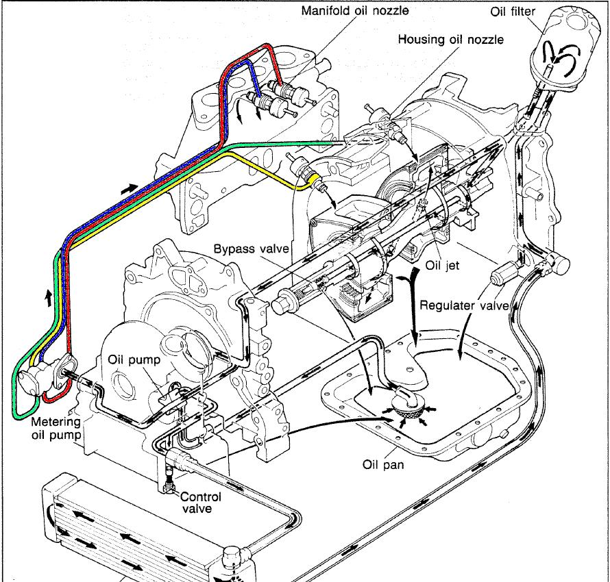
As seen in the below Mazda training manual diagram, the OMP is attached at the front passenger side of the engine.
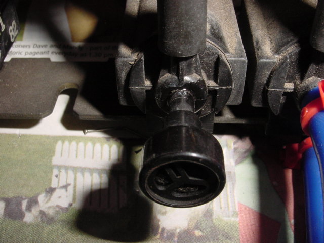
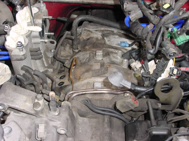
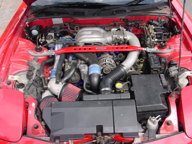
In the below pictures you can see a picture of the OMP on the engine, with the hose leading up to the engine as well as the location of the OMP housing injectors under the intake manifold.
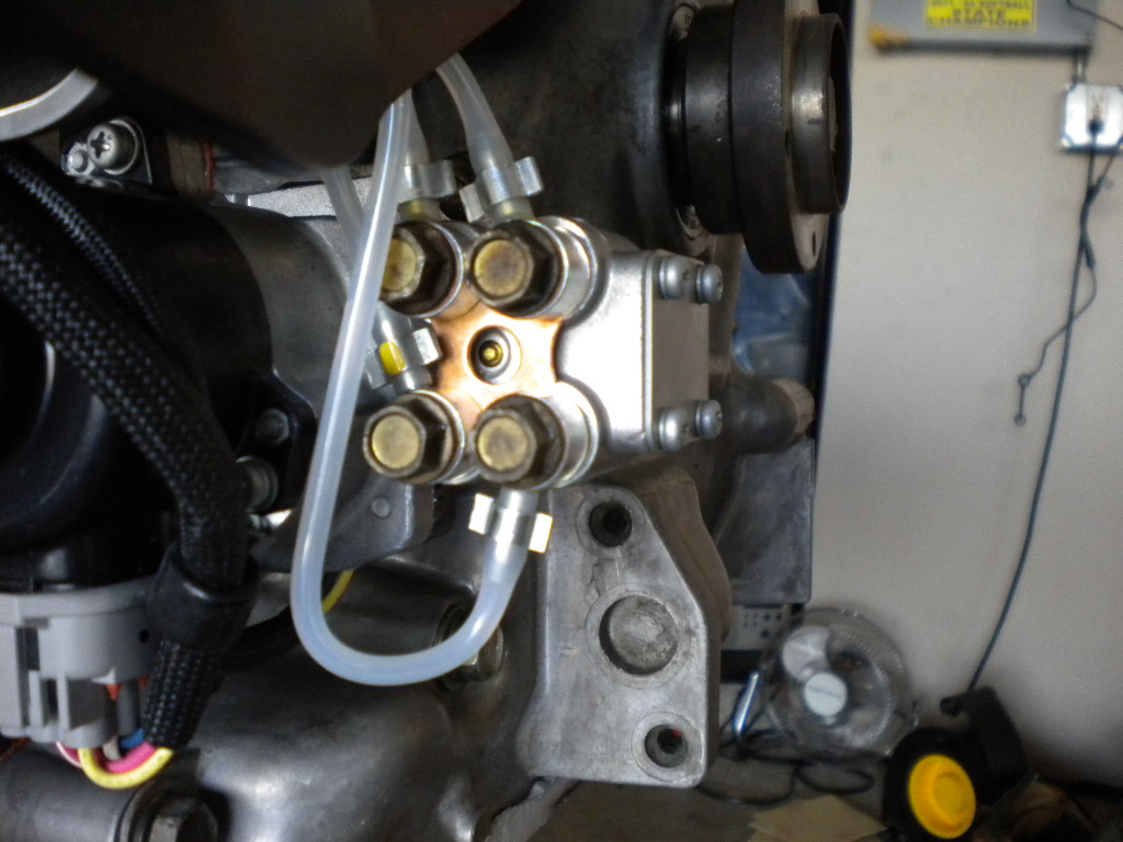
(Above) OMP on engine
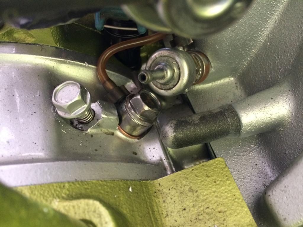
(Above) OMP Rotor Housing Injector
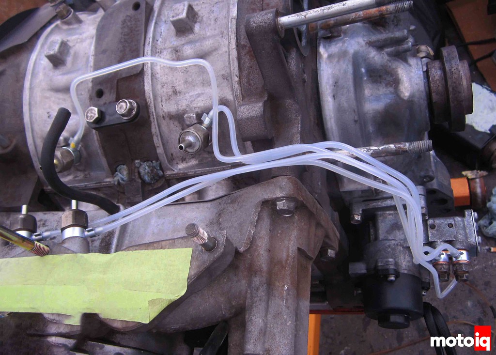
(Above) OMP system in one picture
With the above diagram, and the injectors, you should be able to find the following components for removal.
After removing, you will install the block off plate in place of the OMP (remember to use an oil compatible sealant, like permatex black!)
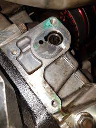
(Above) OMP is removed.
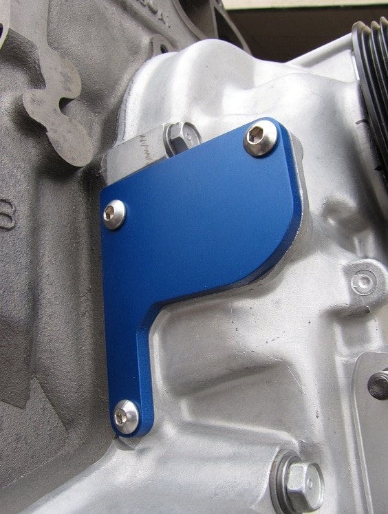
(Above) OMP is blocked off
With the main pump system removed, you will also install 4 injector plugs in the rotor housing,
DO NOT OVERTIGHTEN THESE YOU WILL DIMPLE THE HOUSING OUT AND DAMAGE YOUR ENGINE.
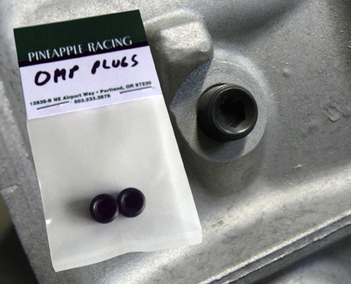
With these plugs and block off plates installed, you’ve deleted the oil metering pump!
Removing the Air Pump, BAC, ACV
More Information:
- https://www.rx7club.com/2nd-generation-specific-1986-1992-17/vacuum-distribution-block-question-838397/
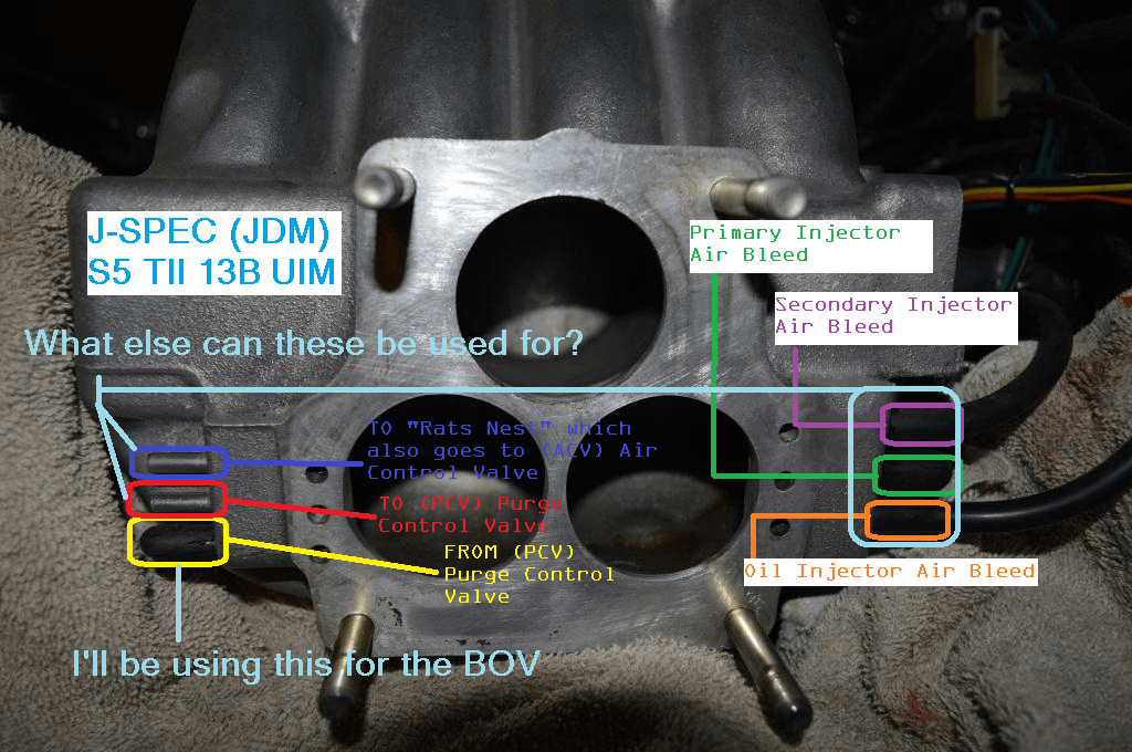
- https://www.rx7club.com/general-rotary-tech-support-11/j-spec-s5-13b-uim-vacuum-identification-1028162/
For the BAC valve, the coolant line starts from a nipple on the rear iron, goes through the thermowax (for the cold start fast-idle function), through the BAC, and then to a nipple on the water pump housing.
Without the ISC, the only air automatic air flow adjuster is the hot wax rod.
(1) Get the engine fully warmed up and idling decently.
(2) Fine tune the idle air flow for best that you can get.
(3) Adjust hot wax rod for needed air flow on a cold start.
If you want to retain the thermowax for the fast-idle function, keep the tube that runs from the rear iron nipple to the thermowax intact. Then run the tube that ran from the thermowax to the BAC straight to the nipple on the water pump housing. If you don’t want to retain this function, you can remove all the hoses (get a container to catch the coolant first) and then just put a cap on the nipples on the iron and housing. Make sure to use a hose clamp on the cap to prevent leakage.
For the ACV, the hose comes from the air pump on the front to the ACV, then through the ACV it comes out going to the catalytic converter. The function of the ACV was to divert this air into the exhaust ports depending on engine speed.
If you still have the air pump and catalytic converter and wish to keep them functional, connect the tube from the air pump straight to the tube that goes to the catalytic converter. I haven’t tested this myself, but can’t see why it wouldn’t work. If you want to remove them, you can remove the air pump and the catalytic converter and not worry about it (depending on local emissions laws). I ran with my catalytic converter installed but not receiving any air for awhile, and I didn’t notice anything too unusual, but Mazda designed the system that way for a reason so I’ll defer to their judgement and advise that you either keep them together or get rid of both (again, depending on local emissions laws).
This is where it becomes a bit of a rabbit-hole: Removing the air pump also requires a dual-pulley for the alternator with two belts. This is because the same belt that drove the air pump was also one of two belts that ran the water pump, the other belt being the alternator belt. Running with just one belt is inadvisable, since (again) Mazda designed that pulley to have two belts for a reason. Slippage could cause the water pump to not pump enough, causing overheating. Also, removing the catalytic converter means that the split-air tube doesn’t run up to the car anymore. If you have a Series 4 car, the split-air tube provided the pressure to open the auxiliary ports, meaning you’ll need to wire them open or find an alternative way of providing the pressure to open them. If you have a Series 5 car, the air pump provided the pressure to open the auxiliary ports, meaning you’ll (again) need to wire them open or find an alternative way of providing the pressure to open them. If you have a Racing Beat exhaust, the new tube is provided for you on the header. If you wire the ports open, you’ll lose low end torque below 4000 rpm.
https://www.rx7club.com/new-member-rx-7-technical-256/cat-air-pump-schematic-940050/
1) For the handful of ACV connections, use standard 3.5mm vacuum hose. Nothing special. To hook up a split air pipe, you can use some generic emissions/heater hose.
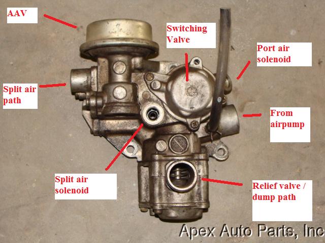
2) The AAV is just part of the ACV. The diagram at the top of the page in that link is a blown up view of the ACV, and the things it connects to. The relief valve, switching valve, split air valve & port air valve are all inside the ACV. The split air and port air solenoids are on the outside of the ACV, and have plugs that connect up to the harness. I’ve labeled the picture you linked to, but I can already see the split air and port air solenoids are missing. You could thread some bolts into the openings and still pass smog. Their use is limited; however I think you’ll end up with the check engine light coming on: http://www.johnr.com/cpucodes.html. This could fail you.
3) The emissions rack is just what’s attached to the top of the block (under the intake manifold), that has all of the vacuum lines and fuel lines routed through it. There would be something like 5 large black solenoids with colored plugs attached.
Now something else to consider…
With no air pump and no ACV, your S5 NA is almost definitely suffering from a severe lack of power. The auxilliary intake port actuators and VDI (variable dynamic intake) actuator are activated by solenoid using air pump pressure. They’re responsible for approx. 40HP. There’s the possibility that someone “wired” everything open, which means low RPM torque will suck.
Delete Everything
(Above) UIM bottom right is Boost ref/MAP sense
(Above) Shows various block off plates installed on upper and lower intake manifold.
(Above) rear iron coolant outlet port is shown routed direct to return on water pump housing
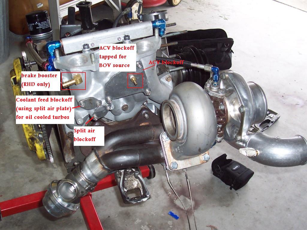
Note, in the above picture, the split air block off and coolant passage are blocked off.
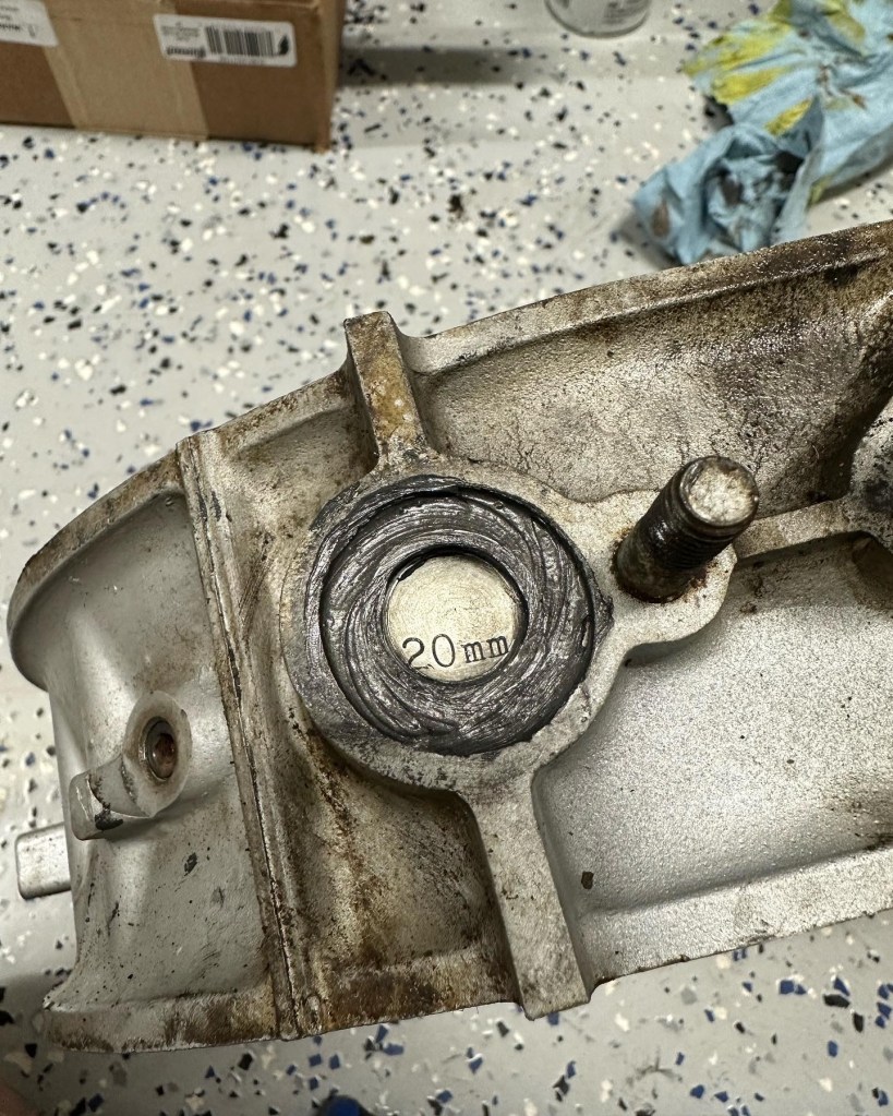
After removing the air pump, the idle air control valve, the bypass air valve, the entire rats nest, the vacuum chamber, etc. you will want to cap ALL the open vacuum ports. any openings should have block off plates installed. In addition, you will have coolant flowing through the back 2 intake runners on the LIM.
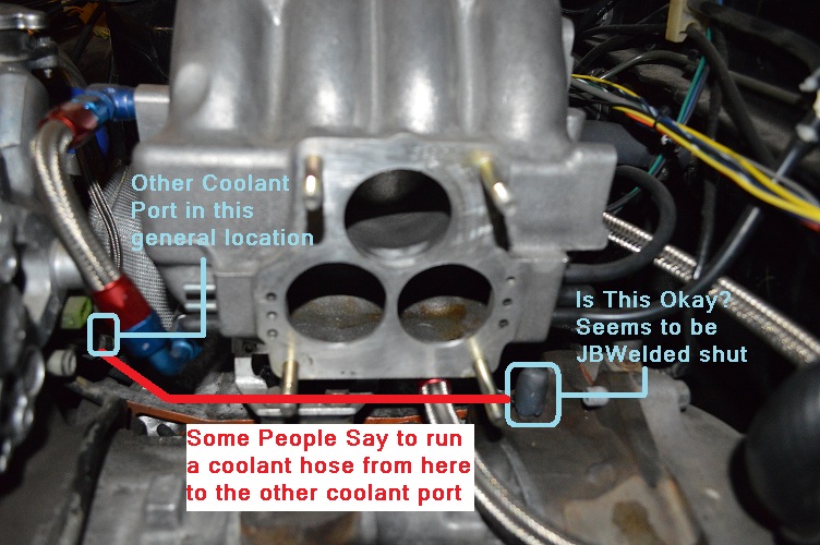
If a coolant source is needed for a turbo, the factory coolant feed port can be utilized; however, if an oil cooled turbo is used, it is recommended to block this coolant channel off using a 20mm freeze plugs and silicone sealant as shown in the picture below. This requires removal of the lower intake manifold (best performed during assembly of the engine).